By Solenoid Switch 2061
What is an electromagnetic switch?
Features and functions of electromagnetic switches
Core principle and working mechanism
Practical applications and scenarios
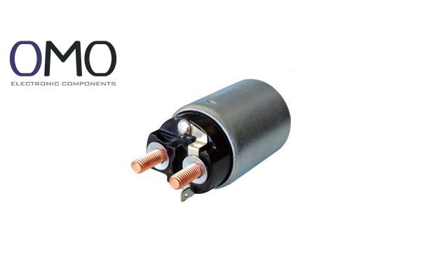
An electromagnetic switch (also called a magnetic starter or electromagnetic relay (relay for high-power)) is an electromechanical device. It uses electromagnetic force to open or close a circuit. Its main job is to use a small control signal to remotely and automatically switch a large working circuit. This “small control, large power” feature makes it a base element in electrical control.
The word “solenoid” comes from Greek. It means “tube-like” or “channel-like”. It refers to the main part — a coil wound on a cylinder. When current flows in the coil (solenoid (coil that makes a magnetic field)), it creates a magnetic field. The word “switch” shows the final function. “Solenoid switch” thus means a switch driven by magnetic force.
A typical electromagnetic switch has two main parts: the electromagnetic system (drive part) and the contact system (actuating part).
Electromagnetic system (drive part)
Contact system (actuating part)
Electromagnetic switches are widely used because of these key features:
From these features, the electromagnetic switch gives these main functions:
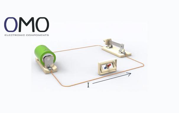
The switch works by the magnetic effect of current (Ampere’s law (current makes a magnetic field)). A current in a wire makes a magnetic field. If we wind the wire into a coil, we focus and strengthen the field. We use that field to move parts and switch the circuit.
The working process has clear steps:
Electromagnetic switches appear in almost every electrical field. Below are typical examples:
| Application area | Equipment / Scenario | Description |
| Automotive industry | Starter motor (starter motor) | Use a small control current to control the battery’s large current to the starter motor (up to hundreds of amps). It is key to start the engine. |
| Industrial control | Motor control cabinet (AC contactor (AC contactor for three-phase motors)) | Control start, stop, and forward/reverse of three-phase induction motors. It is a core part of factory automation. |
| Home appliance | Washing machine, dishwasher | Control water inlet and drain valves. They open and close automatically. |
| Power systems | Distribution circuit breaker (circuit breaker) | Act as the operating mechanism for remote open/close of breakers. |
| Security systems | Electromagnetic lock (magnetic lock) | When powered, the lock holds the door by magnetic force. Power off releases the lock for access control. |
Compared to manual switches or solid-state relays (SSR (solid-state relay)), electromagnetic switches show clear advantages in some areas.
Advantage 1: versus manual switches
The main advantage is safety and automation. Operators do not touch the high-voltage main circuit. Remote control lowers risk. In industry, using electromagnetic switches for remote control can reduce the chance that a worker touches high voltage by about 95%. Also, you can easily integrate them into automatic control systems. Manual switches cannot do this.
Advantage 2: versus solid-state relays (SSR)
For very large current cases (for example over 50 A for motor control), electromagnetic switches (contactors) use physical metal contacts. They have small voltage drop when on (often below 2 V). This makes low heat and high efficiency. A similar solid-state relay has a larger voltage drop (often 1.5–2 V or more). It needs big heatsinks. The system size and cost rise.
Example for a 40 A three-phase motor:
Electromagnetic switch (contactor):
Solid-state relay (40 A):
Main advantages summary:
Knowing common faults helps find problems fast. The table lists typical fault signs and likely causes:
| Fault symptom | Symptom description | Possible cause |
| Cannot pull in | Coil is powered, but no sound and main circuit stays open. | Coil burned open (coil open), control power failure, mechanical jam. |
| Weak pull-in / loud noise | You hear a “buzz” and the pull force is weak. | Supply voltage too low (below 85% of rated), dirt or rust on the iron faces, broken shorting ring. |
| Overheating | The switch housing feels very hot. | Large contact resistance causes heat, coil turn-to-turn short, long-term overload. |
| Contact welding (sticking) | After coil off, the main circuit still carries current. | Contacts welded by arc, load short, very heavy overload. |
| Cannot release | After coil off, the armature does not return. | Oil or dirt on the iron face, spring fatigue or failure, mechanical jam. |
Regular maintenance keeps the switch working well.
Regular checks:
Cleaning:
Mechanical part care:
Check that the armature, shaft, and moving parts move freely. No jams.
Add a very small amount of grease (for example petroleum jelly) to pivot points if needed.
Advantage 3: maintenance ease
Compared to highly integrated electronic modules, electromagnetic switches have modular mechanical parts. This makes them easy to maintain. On failure, a technician can often find the problem by simple checks (look at contact burn, hear the coil, measure coil resistance). They can replace the coil, contacts, or springs directly, or replace the whole switch. The MTTR (mean time to repair) is short. Complex electronic module repair often needs special tools and skills.
Correct wiring keeps people and equipment safe. Below we use a common three-phase AC contactor (three-phase contactor (AC contactor)) as an example.
(To be safer, place the thermal relay’s NC contact in series after the stop button.)
An electromagnetic switch operates by employing an electromagnet (solenoid) to transform electrical energy into mechanical movement, which then activates the switch. Its core component is a coil wrapped around an iron core; when energized, the coil produces a magnetic field.
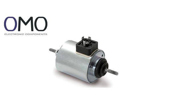
A solenoid switch is an electromechanical actuator that integrates a solenoid with a switching mechanism. Its automotive application involves energizing the starter motor, whereas in industrial machinery, it is employed for the switching operations of motors and various electrical devices.
Symptoms of a defective solenoid switch can range from a silent, unresponsive unit when power is applied and sporadic starting performance to electrical issues such as an open coil (high resistance) or a short circuit (low resistance).
A solenoid switch goes by various names—such as solenoid relay, electromagnetic switch, starter solenoid, contactor, or valve solenoid—based on its function, construction, or field of use.