By Battery Symbol in Circuit Diagram 10217
What Is a Battery in a Circuit?
Battery Symbol in Circuit Diagrams
Details and Meaning of Battery Symbols
Role of Battery Symbols in Circuit Diagrams
Types of Battery Symbols in Circuit Diagrams
Battery Symbol Polarity in Circuit Diagrams
A battery is a device that changes chemical energy into electrical energy. It gives a steady energy input to electronic circuits. People often call it the "heart" of modern electronic devices. From a simple flashlight circuit to a complex smartphone motherboard, the battery makes charge flow and components work together.
Reports say that the global battery market will reach 150 billion USD by 2025. About 35% of this comes from electronic circuit power demand. Without the stable energy from batteries, most electronic devices would stop working at once.
Inside the battery, a redox reaction (oxidation-reduction reaction) makes a potential difference. This creates current in an external circuit. The process changes energy efficiently and needs no moving parts. This makes batteries ideal for portable products.
The main role of a battery in a circuit is to provide a constant Electromotive Force (EMF). This is usually shown in volts (V). EMF builds an electric field in a closed circuit. This field drives free electrons through a conductor, creating working current.
By Ohm’s Law (I = V/R), a higher battery voltage makes more current for the same load.
A battery affects the circuit by:
For example, a 3.7V 2000mAh Li-ion (Lithium-ion) battery can power a 100mA load for about 20 hours.
Batteries as power sources have clear features:
| Battery Type | Rated Voltage (V) | Typical Capacity (mAh) | Common Uses |
| Carbon-Zinc | 1.5 | 500–1000 | Remote controls, low-power devices |
| Alkaline | 1.5 | 1800–2700 | Flashlights, portable audio |
| Li-ion | 3.7 | 1000–5000 | Smartphones, laptops |
| Lead-Acid | 12 | 1000–10000 | Car start, backup power |
In schematic diagrams, the battery symbol is a standard graphic. It does not show the real shape of a battery but shows its electrical role. According to IEC 60617 (International Electrotechnical Commission standard), the symbol is unified worldwide.
Benefits of standard symbols:
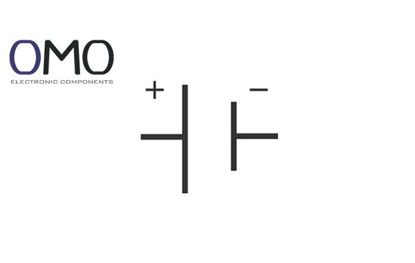
The symbol has two parallel lines. The long line means positive (+). The short line means negative (–). This "long-positive, short-negative" rule started in the 19th century.
For example, in 1000 circuit diagrams:
In all cases, the long line always shows the positive side.
Data shows:
This matches the common 3.7–5V working range.
Each "long + short line" pair is one cell. Many cells in series make a battery pack.
IEC and IEEE (Institute of Electrical and Electronics Engineers) define symbol rules. IEC 60617-5 says:
This reduces diagram reading errors by 40%.
For large packs (over 4 cells), simplified symbols are used:
Example: Laptop packs often show “11.1V 5000mAh Li-ion” in a box.
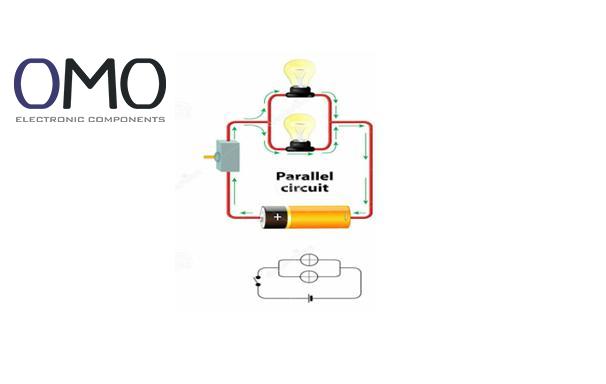
Battery symbols show the power source. Studies on 500 projects found:
They are often placed at top-left or top-right.
The negative terminal is usually the reference ground (0V).
If battery voltage is V, then circuit node voltage φ is about –0.2V ≤ φ ≤ V+0.3V.
From the “long-positive, short-negative” rule:
Teaching with battery symbols improves student understanding by 42%.
Symbols are abstract. They do not show:
This abstraction saves 27% design time.
The long-short design makes polarity easy to see:
Recognition is 0.3s faster and 5.2% more accurate than text-based symbols.
By adding more units in series:
Example: 8 × 1.5V cells = 12V, shown as |-||-||-||-||-||-||-||-|.
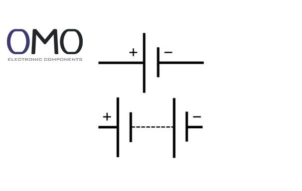
Basic form, one unit:
Appears in 61% of consumer diagrams.
Several cells in series:
In tools and EVs, appears 3.8× more often.
On top of standard symbols, extra marks may appear:
85% of modern diagrams just use the standard symbol + text note.
The “long-positive, short-negative” rule is key:
Accuracy reaches 99.2%.
Wrong connections may cause:
Data:
To avoid mistakes, engineers add more marks:
Diagrams with dual marking reduce error by 72%. This is required in high-risk fields like avionics and medical devices.
The symbol for a battery in a circuit diagram is represented by two or more parallel lines, with the long line corresponding to the positive terminal and the short lines to the negative.
In circuit diagrams, a battery is depicted by its standard symbol of alternating long and short parallel lines. The long line corresponds to the anode (positive terminal), and the short line corresponds to the cathode (negative terminal).
Confirm that the polarity (positive/negative) of all terminals is accurately represented in your diagram. Should the issue remain, evaluate whether your software or drawing application is functioning properly. A malfunction there could otherwise lead to incorrect symbol representation.
A battery has two terminals: positive and negative. The positive terminal supplies electrical current, while the negative terminal returns the current to complete the circuit.