A transformer is a key part of modern power systems and electronic devices. It is a static electrical device that uses the principle of electromagnetic induction to transfer electrical energy. Its main job is to raise or lower alternating current (AC) voltage, while keeping the frequency the same. Unlike generators or motors, a transformer has no rotating parts. This makes it efficient, quiet, and very reliable.
A transformer does not create or use energy. It only transfers it efficiently. In ideal conditions, its transfer efficiency is nearly 100%. In real use, because of losses (like copper loss and iron loss), high-end products can still reach 97% to 99.5% efficiency. This high efficiency is important for long-distance power transmission and precise power distribution. Another key role is electrical isolation, which keeps devices and people safe. It also helps match impedance (resistance in AC circuits) to improve power transfer.
Key Components Breakdown
Core: Made of stacked silicon steel sheets with high magnetic permeability. It forms a low-resistance magnetic path to guide magnetic flux. The core’s quality affects efficiency and heat rise.
Windings:
Primary winding: The coil that receives input energy. Made of copper or aluminum wire.
Secondary winding: The coil that outputs energy. The turns ratio (N₁/N₂) decides the voltage change ratio (V₁/V₂).
Insulation system: Multi-layer protection between windings and ground. Uses materials like insulation paper, Nomex, and epoxy resin. It ensures long-term safety and reliability.
Cooling system:
Oil-immersed: Uses transformer oil for cooling (natural or forced circulation). Often combined with air or water cooling.
Dry-type: Uses natural air cooling or forced air cooling.
Enclosure/Oil tank: Protects internal parts. Oil-filled transformers need sealed tanks to prevent leakage. Dry-type cases need good ventilation.
Tap changer (optional): Adjusts the effective turns of the winding to fine-tune the output voltage (±5% or ±10%) for grid voltage changes.
Main Applications
Power Systems
Transmission: Power plants produce electricity at medium voltage (e.g. 10kV–20kV). Step-up transformers raise this to high voltage (e.g. 110kV, 220kV, 500kV, or even 1000kV) to reduce current and lower transmission loss (I²R loss). Doubling voltage cuts loss to 1/4 at the same power. High-voltage lines usually lose only 5%–8%, but lower voltage lines may lose 12%–15%. Step-up transformers are essential for this.
Substations: Use step-down transformers to reduce high voltage to 35kV or 10kV for city or industrial use.
Distribution: Distribution transformers (usually <2500kVA) installed on poles, ground, or indoors reduce 10kV to 400V/230V (three-phase) or 120V/240V (single-phase) for users. Their efficiency affects power cost and quality. Efficiency is highest at 40%–80% load.
Key Impact: Transformers connect power production to end use. They enable long-distance, large-capacity, and flexible power delivery. Without them, modern centralized power systems and large grids would not exist.
Industrial Use
Large equipment supply: Provide correct voltage for heavy motors (like 1000s of kW), induction furnaces, and large frequency converters.
Rectifiers and traction: Rectifier transformers supply DC to electrolysis, electroplating, and transport systems (trains, subways).
Special loads: Arc furnace transformers handle very high current (tens of thousands of amps). They offer wide voltage adjustment (±20% or more) to meet smelting needs.
Safety isolation: Isolation transformers (1:1 ratio) cut direct connection between input and output. They protect workers and equipment. Very useful in automated lines with many frequency converters.
Electronics
Power adapters: Convert 230V AC (or 120V AC) into low-voltage DC (e.g. 5V, 9V, 12V, 19V) for phones, laptops, routers. These use small low-frequency or high-frequency transformers.
Switching power supply (SMPS): Use high-frequency transformers (kHz–MHz range) as the key magnetic part. They are much smaller and lighter than normal transformers.
Signal processing: Audio output transformers match speaker impedance to get maximum power. Network isolation transformers give electrical isolation and reduce noise in Ethernet.
Other Fields
Instrument Transformers:
Voltage Transformer (PT/VT): Reduce high voltage (like 110kV) to safe levels (like 100V) for measurement and protection.
Current Transformer (CT): Reduce high current (hundreds to thousands of amps) to lower levels (e.g. 5A) for metering. CT must never be open when in use.
Medical devices: Special transformers in X-ray machines create very high DC voltage (tens of thousands of volts).
Welding machines: Arc welding transformers give steady low voltage, high current (e.g. tens of volts, hundreds of amps) with a steep voltage drop for welding needs.
Core Principle
The basic working principle of a transformer is Faraday's Law of Electromagnetic Induction: A changing magnetic field can create an electromotive force (EMF) in a conductor. Lenz's Law explains that the direction of this current always works against the change in magnetic flux that causes it.
Detailed Working Process
Primary Winding Excitation:
An AC input voltage V₁ goes to the primary winding (N₁ turns). This creates a small exciting current I₀ (almost the same as magnetizing current when no load is connected). I₀ builds the working magnetic flux.
Alternating Magnetic Flux Generation:
I₀ produces a main magnetic flux Φ in the closed iron core. This flux changes in a sine wave shape over time. The rate of change (dΦ/dt) decides the induced voltage.
Secondary Winding Induction:
The main flux Φ also links with the secondary winding (N₂ turns). According to Faraday's Law, it induces an EMF:
E₂ = -N₂ × (dΦ/dt).
The frequency of this voltage is the same as the input.
Voltage Conversion Formula:
In an ideal transformer (no resistance, leakage inductance, core loss, or magnetizing current), the effective voltages V₁ and V₂ are in proportion to the number of turns N₁ and N₂:
V₁ / V₂ ≈ N₁ / N₂ = k (where k is the turns ratio).
The input voltage V₁ relates to the magnetic flux Φₘ by the formula:
V₁ ≈ 4.44 × f × N₁ × Φₘ,
where f is the power supply frequency. This shows that both frequency and number of turns affect magnetic flux.
Current Conversion Formula:
An ideal transformer follows energy conservation (ignoring losses):
V₁ × I₁ ≈ V₂ × I₂ (I₁ and I₂ are the effective values of the primary and secondary currents).
Using the voltage formula:
I₁ / I₂ ≈ V₂ / V₁ ≈ N₂ / N₁ = 1/k.
So, current is inversely proportional to voltage and number of turns.
Working with Load:
When the secondary side connects to a load Zₗ, current I₂ flows.
The magnetomotive force (I₂ × N₂) tries to reduce the main flux Φ.
To keep Φ stable (to ensure V₁ ≈ 4.44 f N₁ Φₘ), the primary draws an extra current I₁ₗ from the power supply. This creates a force I₁ₗ × N₁ that balances I₂ × N₂. So the total primary current is:
I₁ = I₀ + I₁ₗ.
At this time, I₁ₗ and I₂ have nearly opposite phases, and:
I₁ₗ / I₂ ≈ N₂ / N₁ = 1/k.
The no-load current I₀ is very small.
Shape Based on Use
Category
Main Types
Common Applications / Features
Power Transformer
Step-up and Step-down Transformers
Power grids (>35kV), large substations, up to hundreds of MVA
Distribution Transformer
Used for end users (≤35kV)
Medium to low voltage, usually ≤2500kVA
Special Transformer
Rectifier Transformer
For DC in electrolysis, electroplating, railways
Furnace Transformer
Low voltage, high current, wide voltage adjustment
Test Transformer
Makes high voltage for equipment testing
Instrument Transformer
Voltage Transformer (PT/VT)
High voltage measurement and protection
Current Transformer (CT)
High current measurement and protection
Voltage Regulating Transformer
Contact-type autotransformer
Adjustable AC output voltage
Isolation Transformer
Turns ratio 1:1
For electrical isolation and safety
Cooling Methods
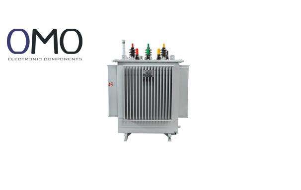
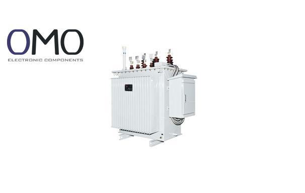
Oil-immersed Transformer (Mainstream):
High cooling efficiency: Oil has better heat capacity and conduction than air. Good for medium and large transformers.
Good insulation: Oil gives strong insulation and arc-extinguishing ability.
Disadvantages: Risk of oil leakage and fire (needs fire protection). Also has environmental problems (waste oil treatment). Needs regular oil tests and maintenance.
Maintenance Comparison:
Usual maintenance every 6-12 months (check oil level, temperature, bushings, etc.). Fire risk requires fire pits and safety systems, which increases setup complexity and cost.
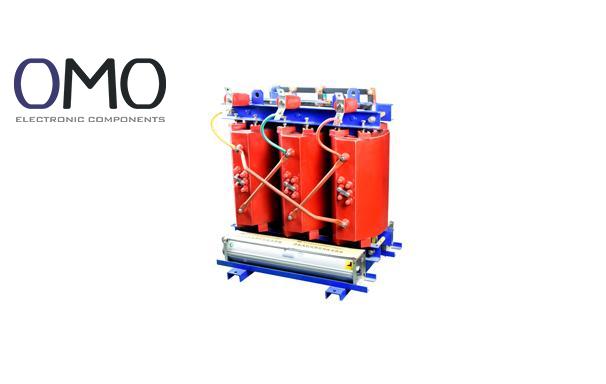
Dry-type Transformer (like epoxy resin cast):
High safety: No oil, great fire and explosion protection. Meets top fire safety level (like F1 class). Best for crowded areas (subways, malls), hazardous places (mines, chemical plants), and indoor systems (data centers).
Eco-friendly: No oil leakage, no waste oil, more green.
Low maintenance: No oil care needed, high protection level (IP20, IP54 common). In clean rooms, maintenance cycle can be 2–3 years (clean surface, check connections, record heat).
Disadvantages: Bigger size and higher cost than oil type. Cooling is weaker, so not common in large capacity use (>10MVA). Sensitive to dust.
Gas-insulated Transformer:
Uses SF₆ (or eco gas) for insulation and cooling. Fully sealed, small size. Best for limited space (like underground city substations).
But SF₆ is a strong greenhouse gas, so leak and waste must be well controlled.
Structural Diversity and Frequency Adaptation
By Phases:
Single-phase: For single-phase power or as part of three-phase group.
Three-phase: Common for three-phase systems. Uses three iron cores (three-leg or five-leg) and three windings. More efficient than using three single-phase transformers.
By Windings:
Two-winding: Most common. One high-voltage and one low-voltage winding.
Three-winding: Has high, medium, and low voltage windings. Connects systems of different voltages. More efficient (saves 0.5%–1.2% loss).
Autotransformer: Shares part of high and low windings. Has lower loss, smaller size, and cost (saves 15%–25%).
Key limit: No isolation between high and low side. Less safe than isolation type.
By Iron Core:
Core type: Windings wrap around core limbs (like E shape). Common in power use. Easier to check insulation.
Shell type: Iron surrounds windings (like a box). Strong structure, better short-circuit resistance. Used in high current, low voltage like furnaces and rectifiers.
By Frequency (Key Comparison):
Low frequency (50/60Hz): Standard power transformers. Thick silicon steel core (~1.7T magnetic flux). Heavy and large.
Medium frequency (Hz–kHz): Used in induction heating (up to 10kHz). Core uses thinner silicon steel (<0.2mm), amorphous metal, or ferrite.
High frequency (kHz–MHz): Core of switching power supplies. Must use soft magnetic materials (ferrite, amorphous/nanocrystalline, ultra-thin silicon steel).
High Frequency Benefits:
Much smaller and lighter: If frequency ×10, power density can rise ×10 or more. Less material needed.
Loss Challenges:
Core loss (mainly eddy current loss) increases very fast with frequency. Must choose low-loss core.
Copper loss also grows due to skin effect and proximity effect.
Efficiency Trade-off:
High-frequency transformers are smaller, but switching devices lose more energy. A good high-frequency design can reach 85%–94% efficiency. But high-frequency noise (EMI) must be controlled.
Key Advantages of Modern Transformers
Comparison Item
Traditional Solution/Challenge
Modern Solution (e.g. dry-type, high-frequency)
Shown Advantage
Safety
Oil type has leak and fire risks (needs fire system)
Dry-type epoxy cast (F1 fire rating)
Much safer: No fire or explosion risk
Space & Materials
Low-frequency type is big and heavy
High-frequency transformer
Much smaller: Size can drop 50%–90%
Overall Efficiency
Multiple two-winding transformers
Three-winding + new core (amorphous/silicon steel)
Better efficiency: Less stage loss (0.5%–1.2%) + lower core loss (20%–70%)
Frequently Asked Questions
When to use a toroidal transformer?
Opt for a toroidal transformer in applications where low noise (such as audio or medical devices), high efficiency (like in energy-sensitive systems), or a compact footprint (crucial for portable electronics) is essential.
How to use isolation transformer?
First, attach the transformer input to the correct voltage supply (like 220V or 380V) and connect its output to the designated power input on the device. Ensure both the transformer and the device are properly grounded. Prior to installation, confirm the transformer's specifications match your voltage requirements.
How does a dry type transformer work?
Dry-type transformers operate via electromagnetic induction. An alternating current flowing through the primary winding creates a varying magnetic field within the iron core. This changing field, in turn, induces a voltage in the secondary winding, facilitating the transfer and transformation of electrical power.
How three phase transformers work?
The operation of three-phase transformers relies on electromagnetic induction. Three windings share a common iron core, and when energized by three-phase AC current in the primary, they produce a rotating magnetic field within the core.