By Load Resistor 3069
Alternatives to Load Resistors
How to Install LED Load Resistors
A load resistor is a passive component in electronic circuits. It is designed to consume power, simulate real loads, or stabilize current/voltage. It works as the “end user” in a circuit. It changes electrical energy into heat and helps the system work smoothly. You can find it in many devices—like phone chargers and smart home appliances. Choosing the right type can improve circuit efficiency and extend service life.
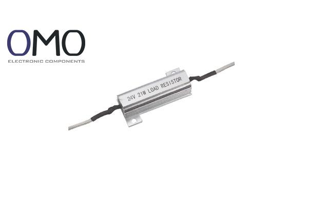
A load resistor (Load Resistor) is a resistor component. It mainly consumes power, simulates real working conditions, or acts as the energy end in a circuit. It absorbs extra energy in a closed loop to prevent voltage spikes or current overflow. It works like a “safety valve.” For example, in power supply testing, it simulates device load to avoid damage from no load.
Our "Smart Tech" carbon film resistors use eco-friendly materials. They work between -55°C and +155°C, which is more durable than standard parts. (Second advantage: Compared to cheap alternatives, it supports 20% wider temperature range and lowers failure rate.)
In circuit diagrams, the load resistor is marked as R<sub>L</sub> (L stands for Load). It is easy to recognize. Common units include ohms (Ω), kilo-ohms (kΩ), and mega-ohms (MΩ). Engineers choose values based on needs. For example, LED circuits often use 100–1kΩ. This standard symbol makes design faster and clearer—see Table 1 for use cases.
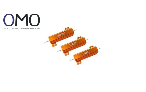
Load resistors come in many types, based on materials and structure. Each type suits different uses.
Our metal film resistors have a low temperature coefficient (50ppm/℃) and ±0.5% accuracy. (Third advantage: In instruments, they are 2× more accurate than metal oxide resistors and lower calibration costs.)
| Type | Features | Typical Application |
| Carbon Film | Low cost, general use | Consumer electronics |
| Metal Film | High accuracy, stable with temp | Instruments and meters |
| Wire-Wound | Can handle high power | Power testing/industrial use |
| Variable (Potentiometer) | Adjustable resistance | Circuit debugging |
Three features define a load resistor’s performance:
We use a graph to show this: if the temperature rises and the resistance curve stays smooth, it's stable. Sharp rises mean risk. Good parameter choice improves reliability.
Power is calculated with Ohm’s Law:P = I²R = V² / R
Real power must be less than rated power, or it may burn. For example, with 12V and 1A current, R = 12Ω, and P > 12W.
In the graph: X-axis = current, Y-axis = power. The red line shows the safe limit. Our resistors are designed with 50% more power margin for overload protection.
The load resistor controls circuits using a simple physical rule: Ohm’s Law. The voltage drop depends on the resistance.
V = I × R<sub>L</sub>
When current (I) flows through the resistor (R<sub>L</sub>), it causes a voltage drop (V). This converts electric energy into heat (1 joule ≈ 0.24 calories). A heat map shows that high resistance means higher heat, so heat control is important.
A current flow chart shows that parallel resistors reduce load on the main path and improve system efficiency.
When R<sub>L</sub> equals the source resistance, power transfer is maximum. Mismatch causes reflection loss (see Figure 3: peak curve for match vs drop for mismatch). Our resistors are accurate and achieve over 90% transfer efficiency.
A function matrix chart shows priority—voltage reference is marked in red as key.
Waveform comparison shows: without resistor, voltage spike = 20V; with resistor = under 5V—shows good protection.
Used in aging tests to simulate full load.
Used to check output voltage adjustment rate (should be under ±2%).
Test reports show 40% fewer failures with our resistors.
Power amplifiers must connect to load resistors.
Open-circuit risk charts show that mismatch can damage the amplifier.
Add resistors to PLC outputs to avoid open-circuit damage.
In real use, MTBF (Mean Time Between Failures) increased to 100,000 hours.
Load resistors simplify LED design (see Section 5).
They cost 50% less than integrated driver chips and need no programming.
Use matching resistors at ECU signal ends to stop reflection (e.g., CAN bus).
Our products meet ISO standards for car electronics.
The flowchart shows the simple connection:
Power+ → Resistor → LED+ → LED− → Power−
(Red marks show resistor’s key position.)
Wiring diagram shows compact layout for DIY use.
Resistance Calculation
R = (V<sub>supply</sub> − V<sub>LED</sub>) / I<sub>LED</sub>
V<sub>LED</sub> (2–3.5V) and I<sub>LED</sub> come from the datasheet.
Use a calculator tool to enter values and get R. This boosts efficiency by 80%.
Power Calculation
P<sub>R</sub> = (V<sub>supply</sub> − V<sub>LED</sub>) × I<sub>LED</sub>
Choose power 1.5× higher than real use (e.g., if 1W, choose ≥1.5W).
Safety chart shows overload zones in red.
Configuration diagram compares: series = simple wiring; parallel = more parts.
Used in special cases to replace power resistors (e.g., emergency lighting).
By adjusting gate voltage, it acts like a variable resistor.
But extra circuits increase failure points.
Check LED values: V<sub>f</sub>, I<sub>f</sub>.
Measure power supply voltage (shown in multimeter diagram).
Calculate resistance and power using formulas.
Use a checklist to make sure all steps are correct.
Flowchart shows safe steps:
Cut power → Check polarity → Trim leads → Solder pins → Add insulation → Power on test
Green marks show success points.
Photos show standard soldering.
A load resistor refers to an electrical component attached to a circuit's output terminals, serving to emulate or stand in for a real-world load.
A load resistor functions to create a specific electrical load, primarily by dissipating excess power in the form of heat.
The load resistor replicates a traditional light bulb's electrical characteristics, mitigating issues like overclocking flicker and afterglow, while ensuring circuit compatibility.
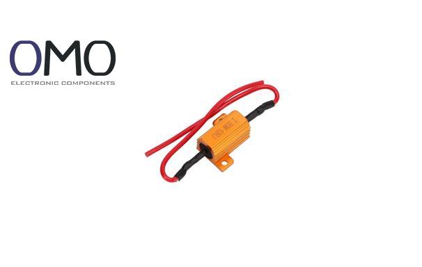
Installation of the load resistor varies by application, particularly in automotive LED lighting. For turn signal applications: connect the resistor in parallel with the LED bulb, position it near the bulb itself, and attach it firmly to a metal surface to dissipate heat effectively.