By Multimeter 3671
Functions and Technical Principles
Application Scenarios and Practice
Common Problems and Maintenance
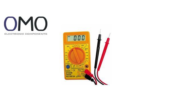
A multimeter is a portable instrument that combines voltage, current, and resistance measurement. People call it the “Swiss Army knife” for electricians and electronic engineers. The main parts include a display (digital) or dial (analog), a knob, ports, and test probes. It is easy to use and has many functions. Whether fixing home circuits or working on precise electronics, a multimeter gives useful data support.
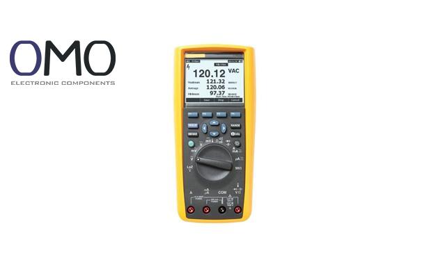
Product Advantage Comparison: Traditional analog meters use pointer readings, which can be wrong due to viewing angles. But a certain brand’s digital multimeter uses a high-contrast LCD screen, which stays clear under sunlight. It also has a low error rate of ±0.5%, making measurements faster and more accurate.
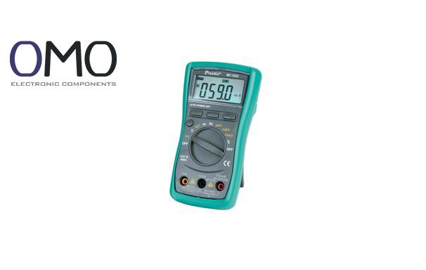
Multimeters are either analog (pointer type) or digital (LCD/LED). Digital ones are now more common because of auto-ranging and high accuracy. Special types include clamp meters (for measuring large current) and True RMS (Root Mean Square) meters (for non-sinusoidal wave signals).
| Type | Analog Meter | Digital Meter | Brand Flagship Model |
| Accuracy | ±2% | ±0.5% | ±0.1% |
| Response Speed | Slow | Fast | 0.1-second instant read |
| Usage Scenario | Basic repair | General use | High-precision industry |
Voltage is measured in volts (V), current in amperes (A), and resistance in ohms (Ω). For example, a home socket has about 220V. A phone charger uses about 2A. A common resistor may have resistance from 1Ω to 1MΩ.
Besides basic measurement, advanced multimeters can test continuity, measure capacitance (F) and frequency (Hz), or use a temperature probe to monitor from -40°C to 1000°C. For example, one model has a built-in True RMS chip to measure complex signals from inverters, with less than 1% error.
Product Advantage Comparison: Normal multimeters test capacitors under 10μF. A certain brand’s product, with optimized circuits, can test large capacitors up to 20000μF. This helps with industrial motor maintenance.
Measures voltage difference. “V⎓” stands for DC (Direct Current) like batteries. “V~” is for AC (Alternating Current) like wall outlets. “mV” is used for small voltages in low-power electronics.
Measures electric flow. “A⎓” is DC, and “A~” is AC. Small ranges like “mA” (milliamps) or “µA” (microamps) are used to test small currents and check power use.
“Ω” shows how much a material resists electric flow. This helps check if circuits are open or find broken parts.
It uses sound to show if a circuit is complete. If the circuit is okay, the meter makes a beep. This helps fix circuits faster.
Used to check diodes. It measures forward voltage drop to test if the part works properly.
Shows how much energy a capacitor can store. It’s important when installing or checking capacitor parts.
This symbol means a common ground point. Usually, it's connected to the metal case or earth ground to give stable readings.
Keeps the current reading on screen. This helps record or compare data.
After setting a reference value, it shows the change from that value. This is useful to track small changes.
Shows power level of the multimeter. Low power may cause wrong readings, so replace the battery in time.
A minus sign shows reversed test leads. Make sure the probes are connected correctly.
Shows that the range is too low. You should switch to a higher range to avoid damage.
Decimal point and unit symbol (like kΩ, µA) give full measurement value. Understanding them helps avoid big mistakes.
From home repair to factory testing, multimeters meet many needs. For example, an engineer used a True RMS meter to test an inverter. He found high harmonic distortion, which helped avoid motor damage.
Case Study:
Smart Anti-Misplug Design: One brand uses color-coded and lockable ports. This reduces user errors by 75% compared to regular products.
Blown fuses cause 60% of problems. This often happens when using the current setting on high voltage. Some brands use ceramic fuses and auto-reset protection, which are three times stronger.
Mistake: Using the resistance mode on a live circuit can damage the voltage reference.
Solution: One model has real-time voltage warning. It beeps if the circuit is live.
The multimeter's resistance setting is indicated by the omega symbol (Ω), corresponding to the unit of electrical resistance known as the ohm.
On multimeters, electrical current measurements are indicated through standardized abbreviations: the ampere symbol is denoted by "A", representing the base unit of electric current. Smaller current values use scaled units - "mA" abbreviates milliamperes (thousandths of an ampere), while "µA" stands for microamperes (millionths of an ampere).
The symbol for alternating current voltage is typically denoted by V~ or volts AC. This notation finds widespread application in electrical systems and infrastructure, including domestic power outlets, industrial equipment applications, and electricity distribution networks such as national grid systems.
The resistance threshold needed to activate the audible alert differs among multimeters. However, the majority of devices will signal proper continuity when measuring within the 0-50 ohm range. An audible tone indicates successful current flow (such as through an intact conductor), while silence suggests a discontinuity in the circuit (like wire fractures or poorly seated connectors).