By Capacitors 3217
Applications and Circuit Design
Dielectric Material Performance Showdown
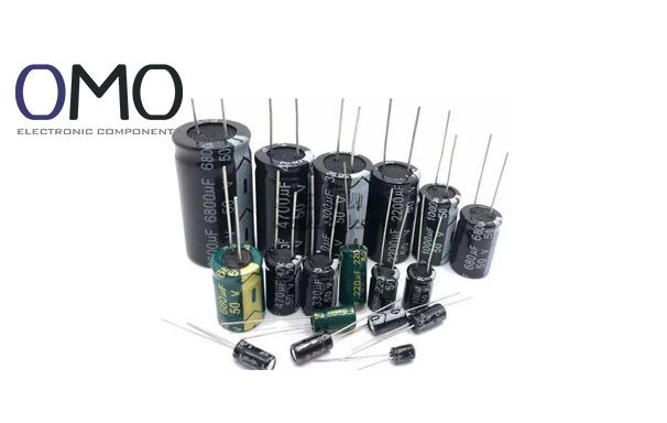
A capacitor is a passive component that stores electrical energy using an electric field. Its core structure consists of metal plates, an insulating dielectric layer, and an outer casing. When a voltage is applied across the plates, positive and negative charges accumulate on either side of the dielectric, creating electrical energy. This principle makes capacitors the “reservoirs” in electrical circuits. For example, aluminum electrolytic capacitors use an aluminum oxide film as the dielectric, and their compact winding process allows a 10μF unit volume to have five times the capacity of ceramic capacitors, meeting the demand for high capacity.
The energy storage formula E = ½ CV² reveals the relationship between capacitor energy and the square of the voltage. A capacitor with a nominal rating of 5V/1000μF can store 12.5mJ of energy, which is enough to make an LED blink 12 times (based on experimental data). Additionally, X-brand solid-state capacitors reduce charging and discharging losses further with their low ESR (Equivalent Series Resistance) characteristic, improving efficiency by up to 20%.
The six-step range from Farad (F) to picofarad (pF) maps the variation in application scenarios: mobile phone RF circuits often use ceramic capacitors of 1-100pF, while industrial variable frequency drives require 1000μF electrolytic capacitors to stabilize bus voltage. Product comparison shows that the A-series high-precision film capacitors with a ±1% tolerance (industry average ±5%) significantly improve the stability of precision timing circuits.
| Parameter | Typical Impact Scenario | Competitor Weakness | Our Solution |
| Rated Voltage | New energy vehicle inverters | Regular products derated to 60% | Enhanced metal film capacitors support 90% full voltage operation |
| Loss Tangent (tan δ) | 5G base station PA modules | Regular ceramic tan δ > 0.02 | High-frequency NP0 material tan δ < 0.001 |
The temperature coefficient is an “invisible killer” for precision instruments: Y5V ceramic capacitors can fluctuate between -80%/+20%, causing frequency offset in filtering. Meanwhile, T-series automotive capacitors use organic silicon composite dielectric, with capacitance variation of <±5% over the -55°C to 125°C range, passing AEC-Q200 certification. Frequency response curves show that when the frequency exceeds 10MHz, the impedance of electrolytic capacitors rises rapidly, while multi-layer ceramic capacitors maintain a flat characteristic.
Golden Rule for High-Frequency Circuits:
An industrial power supply case showed that a reversed tantalum capacitor caused a fire. Solution: Use B-type surface-mount electrolytic capacitors with reverse polarity markings, which extend reverse tolerance time to 5 seconds. The voltage derating curve indicates that at 105°C, the voltage withstand should be reduced to 70% of the nominal value. The super-stable electrolytic liquid technology maintains 85% effective capacity.
5G smart antennas use GaAs varactor diodes (C-V slope 0.2pF/V) to achieve a beam-switching speed of 0.1ms. A comparison table shows that mechanical adjustable capacitors are eight times larger in volume and 150 times slower in adjustment speed than their electronic counterparts (data from ETSI test report).
Supercapacitors have shown great potential in elevator energy recovery. In a subway station renovation case, a three-parallel X-type graphene supercapacitor set achieved a 30% energy savings rate, with over 500,000 charge-discharge cycles. A safety warning regarding capacitor selection: When a Y2 type (300VAC) is incorrectly used in a 380VAC system, the breakdown rate after 1 hour is 100%.
| Type | Scenario Match | Our Innovation |
| Aluminum Electrolytic | Low-cost energy storage | New groove etching process increases capacitance density by 40% |
| Barium Titanate Ceramic | High-voltage fast charging equipment | Gradient sintering process breaks the 20kV voltage barrier |
| Aramid Film | Aerospace power systems | Vacuum impregnation technology enables operation at -200°C |
The capacitor is denoted by the letter C in electrical schematics, a standardized notation used globally to identify this component.
Guide to interpreting capacitor circuit symbols: Start by identifying the standard graphical representation of the capacitor in the schematic diagram. Next, determine whether polarity markings are present on the symbol. Finally, observe the numerical value indicating its capacitance.
The symbol for a polarized capacitor typically features a curved line or arrow to denote its polarity. In contrast, non-polarized capacitors lack distinct polarity markings in their symbol and may be connected in either orientation within a circuit.
The symbol 'C' used for capacitors represents capacitance, which quantifies a capacitor's capacity to store electrical charge, voltage, current, and potential energy.
In a trimmer capacitor, the diagonal lines symbolize its adjustability. Nevertheless, these lines may carry varied interpretations depending on the capacitor's specific type and the context in which it is represented.