By Texas Instruments 111
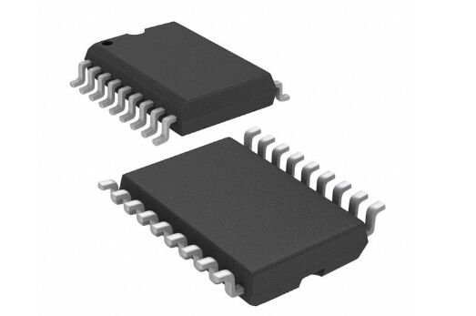
ULN2803ADWR is an integrated circuit that is an NPN transistor array. It contains 8 high-voltage, high-current open collector transistors, which are usually used to drive larger current loads, such as relays, motors, light bulbs, etc. The ULN2803ADWR has an internal reverse recovery diode that effectively protects the output transistor and control circuitry from reverse voltage surges from inductive loads.
ULN2803ADWR, manufactured in Texas, is a Darlington transistor array that can handle higher current gain values in the circuit. It is mainly used in many fields such as automotive, infotainment, communication equipment, broadband fixed-line access, industry, and motor drives.
Ⅰ.Specification parameters of ULN2803ADWR
Package:Reel
Number of pins:18
Drives/Packs:8
Height:2.35mm
Length:11.62 mm
Width:7.52 mm
Humidity Sensitivity:Yes
Configuration:Octal
Transistor polarity:NPN
Installation style:SMD/SMT
Package/Case:SOIC-18
Minimum operating temperature:-40℃
Maximum operating temperature:+85℃
Product Category:Darlington Transistor
Qualification:AEC-Q100
Rated current:500mA
Power dissipation:2.25 W
DC current gain (hFE):500
Maximum allowable current of collector:0.5A
Transistor Type:8 NPN Darlington
Maximum DC collector current:500 mA
Product Type:Darlington Transistors
Product Type:Darlington Transistors
Collector-emitter maximum voltage VCEO:50 V
Vce saturation voltage drop (maximum value) when Ib and Ic are different:1.6V@500µA, 350mA
Ⅱ.Functions and characteristics of ULN2803ADWR
1.Convenient packaging: ULN2803ADWR usually adopts surface mount packaging, such as SOIC (small outline integrated circuit) or TSSOP (thin line gap small outline package), which is convenient for integration into modern electronic equipment.
2.High voltage capability: Able to handle higher voltages, usually operating voltage range is between 3.3V and 50V, suitable for various industrial and automotive electronic applications.
3.High current output capability: The ULN2803ADWR chip has 8 outputs, each output can withstand a current of 500mA, and the total output current can reach
3.5A. This enables it to stably drive high-power loads and meet the needs of different application scenarios.
4.Darlington transistor array: ULN2803ADWR is a Darlington transistor array consisting of 8 NPN Darlington pairs, each Darlington pair has a collector current rating of 500mA. Additionally, the ULN2803ADWR features a common cathode clamping diode for switching inductive loads.
5.Multi-channel output: ULN2803ADWR integrates 8 independent NPN transistor output channels, each channel can drive the load independently.
6.High noise suppression: The design of internal resistors and capacitors helps suppress output noise and interference.
7.Built-in protection circuit: The ULN2803ADWR chip has built-in overvoltage, overcurrent, and overheating protection circuits, which can automatically cut off the output under abnormal conditions to ensure the safety and stability of the system.
8.Integrated input resistor: The input terminal has an internal pull-up resistor, which simplifies the connection with a microcontroller or other digital circuits.
9.Pin Compatibility: Each Darlington pair of the ULN2803ADWR has a 2.7kΩ series base resistor and can operate directly with TTL or 5V CMOS devices.
10.Wide applicability: ULN2803ADWR chip can be used in a variety of application scenarios, such as stepper motor drivers, relay drivers, LED displays, etc. Its output port is an ordinary GPIO interface, which is easy to connect to various microcontrollers and microcontrollers and is flexible and convenient to use.
Ⅲ.Application fields of ULN2803ADWR
1.Automotive electronics: In automotive electronic systems, ULN2803ADWR can be used to drive high-current loads such as automotive lights, electric windows, and wiper motors.
•Car lighting: Car headlights, fog lights, etc. usually require larger currents to light up. The output current capability of the ULN2803ADWR makes it ideal for driving these lights. Through a microcontroller or a specialized light control module, the brightness and flashing frequency of the light can be precisely controlled.
•Electric windows: Electric window motors require a certain amount of current to drive the windows up and down. ULN2803ADWR can provide sufficient current to drive these motors, and through microcontroller control, it can realize automatic lifting and one-key lifting functions of windows.
•Wiper motor: The wiper motor requires a stable current to keep the wipers running normally to remove rainwater from the windows. The ULN2803ADWR's high current output and internal protection circuit ensure stable operation of the wiper motor and provide overcurrent protection to prevent motor damage.
2.LED display: ULN2803ADWR can also be used to drive LED displays. LED displays require a stable current to maintain brightness, and the ULN2803ADWR's high current output and internal current-limiting resistor make it ideal for driving LED displays.
3.Relay driver: Since ULN2803ADWR has high current output capability, it can also be used to drive relays. A relay is a commonly used electrical control device that requires a large current to activate. ULN2803ADWR can provide enough current to drive the relay stably. When using ULN2803ADWR to drive a relay, its input pin can be controlled by the output signal of a microcontroller or other logic circuit, thereby controlling the switching state of the relay. When the output pin of the ULN2803ADWR receives a logic high level, the corresponding Darlington transistor conducts, allowing current to pass through the relay coil, thereby activating the relay.
4.Medical equipment: In medical equipment, ULN2803ADWR can be used to drive various motors, valves, etc. in medical equipment. The ULN2803ADWR's high current output and internal current limiting resistor help provide stable current output, ensuring stable operation of medical equipment. In addition, its fast switching capability also allows motors or other components in medical equipment to respond quickly to control signals.
5.High voltage and high current load control: ULN2803ADWR can also be used to control other high voltage and high current loads, such as solenoid valves, electric doors and electric windows, etc. Because it can provide up to 500mA of current and withstand higher operating voltages (up to 50V), it is ideal for driving load devices that require higher power. Devices such as solenoid valves, power doors, and power windows often require larger currents to activate and perform actions. The ULN2803ADWR's Darlington transistor array can provide the required current, and its internal current-limiting resistor can help protect the device from excessive current.
6.Printers and scanners: In printers and scanners, ULN2803ADWR can be used to drive print heads and scan heads. These devices require precise control of current and voltage to achieve high-quality printing and scanning.
7.Household appliances: In household appliances, ULN2803ADWR can be used to control household solenoid valves, motors, lighting equipment, etc. Solenoid valves in homes are often used to control water flow, such as in automatic faucets or water valves in washing machines. The ULN2803ADWR is able to provide enough current to quickly open and close the solenoid valve for precise water flow control.
8.Stepper Motor Driver: The high voltage and high current output capabilities of the ULN2803ADWR make it an ideal choice for a stepper motor driver. Stepper motors usually require large current and voltage to drive, and ULN2803ADWR can meet this demand.
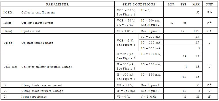
Ⅳ.Electrical Characteristics of ULN2803ADWR
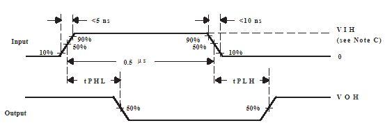
Ⅴ.Voitage Waveforms of ULN2803ADWR
Ⅵ.Thermal management of ULN2803ADWR
•Determinants of thermal management
1.Working environment temperature: If the working environment temperature of the chip is high, the heat generated by the chip itself will more easily cause the temperature to rise.
2.Working mode: If ULN2803ADWR is under working conditions such as high load and high-frequency switching, its internal heating will be more serious.
3.Load current: The greater the load current that ULN2803ADWR can handle, the greater the power consumption inside the chip, and the more heat is generated.
•Thermal management methods
1.Fan: Install a fan near the ULN2803ADWR to enhance air flow and improve heat dissipation efficiency.
2.Optimize layout: Reasonable circuit layout and design can reduce the heat accumulation of the chip and improve the heat dissipation effect.
3.Heat sink: The heat sink can be installed on the surface of ULN2803ADWR to enhance the heat dissipation effect by increasing the surface area.
4.Reduce load current: Reducing the load current of ULN2803ADWR can reduce its internal power consumption, thereby reducing heat generation.
Ⅶ.Alternate model of ULN2803ADWR
•MC1413
•TPIC6B595
•ULN2803A
•STP16CPS05BTR
•ULN2804A
Ⅷ.Steps to use ULN2803ADWR to control relay or motor
1.Connect the input of ULN2803ADWR: Connect the input pin of ULN2803ADWR to a control signal source, such as the output pin of a microcontroller. The input of the ULN2803ADWR is normally pulled up to the supply voltage, so when the input is high, the corresponding output channel will be turned on.
2.Connect the relay or motor to the output of ULN2803ADWR: The output pin of ULN2803ADWR can be directly connected to the control terminal of the relay or motor. For relays, one output channel is connected to the control terminal of the relay, and the relay's coil is connected to an appropriate power source and ground. For motors, one output channel is connected to the control terminal of the motor, while the two terminals of the motor are connected to appropriate power and ground.
3.External protection components: Although ULN2803ADWR integrates diode protection internally, in practical applications, in order to protect ULN2803ADWR and the load, you can consider adding protection components, such as current limiting resistors, reverse diodes, etc.
4.Proper power supply: Make sure both the ULN2803ADWR and the load are connected to the appropriate power supply and ground to ensure proper operation.
5.Control program: Write a control program to control the input signal of ULN2803ADWR to control the switching state of the relay or motor. Corresponding logic can be written as needed to implement different control functions.
Frequently Asked Questions
1.What is the purpose of the internal diodes in ULN2803ADWR?
The internal diodes in ULN2803ADWR are used for flyback diode protection, helping to protect the output transistors and control circuitry from inductive load transients.
2.What is the typical package type of ULN2803ADWR?
ULN2803ADWR is typically available in surface-mount packages such as SOIC (Small Outline Integrated Circuit) or TSSOP (Thin Shrink Small Outline Package).
3.Can ULN2803ADWR be used in low-power applications?
ULN2803ADWR is primarily designed for driving high-current loads and may not be suitable for low-power applications due to its relatively high quiescent current and voltage drop across the output transistors.