By Texas Instruments 1044
The RC4558P is a dual general-purpose operational amplifier (Op-Amp), a common integrated circuit used to amplify voltage signals or perform analog signal processing tasks. Here is some information about the characteristics of this amplifier:
1.High gain:Operational amplifiers have very high gain, which means they can amplify small changes in the input signal. This high gain makes op amps ideal for signal amplification in many circuits.
2.Low output impedance:The output impedance of operational amplifiers is very low, which means that they can effectively drive subsequent circuits or components. This low output impedance makes op amps very useful when building complex circuits because they can easily push the input of other circuit elements.
3.High input impedance:Op amps have very high input impedance, which means they do not consume much energy from the input signal, which allows op amps to interface well with a variety of different types of circuit elements, such as sensors. , without affecting its performance.
4.Offset voltage and temperature drift:Operational amplifiers usually have offset voltage and temperature drift. These factors affect the accuracy and performance of the amplifier and need to be taken into account when designing the circuit. The effects of temperature drift can be reduced by using external components to adjust the offset voltage or taking other measures.
5.Bandwidth limitation:Although operational amplifiers have high gain and low output impedance, their bandwidth is limited. This means they can only handle signals within a certain frequency range. When designing circuits, the bandwidth limitations of op amps need to be considered to ensure that they can effectively handle the required signal frequencies.
6.Supply voltage and current limits:Op amps require supply voltage to function properly, and their power consumption is limited by supply current. These factors need to be considered when designing the circuit to ensure that the op amp will function properly and maintain the required performance.
Ⅰ.Specification parameters of RC4558P
•Manufacturer:Texas Instruments
•Package:Tube
•Slew rate:1.7V/µs
•Product Category:Operational Amplifier-Operational Amplifier
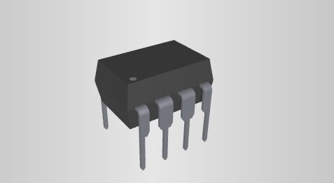
•Package/Case:PDIP-8
•Installation style:Through Hole
•Number of channels:2 Channel
•Shutdown:No Shutdown
•Supply voltage - maximum:30 V
•SR-slew rate:1.7 V/us
•GBP-gain bandwidth product:3 MHz
•Output current per channel:10 mA
•Vos-input bias voltage:6 mV
•Minimum operating temperature:0℃
•Maximum operating temperature:+70℃
•Power supply voltage - minimum:10V
•Ib-input bias current:500 nA
•Voltage-input compensation:500 µV
•Operating power supply current:2.5 mA
•CMRR-Common Mode Rejection Ratio:90 dB
•en-input voltage noise density:8 nV/sqrt Hz
•Amplifier type:General Purpose Amplifier
•Minimum dual supply voltage:+/-5V
•Maximum dual supply voltage:+/-15V
•Dual power supply voltage:+/-9V, +/-12V
•Operating power supply voltage:10V to 30V, +/-5V to +/-15V
•Height:4.57 mm
•Length:9.81 mm
•Width:6.35 mm
•Voltage gain dB:109.54 dB
Ⅱ.Pin distribution of RC4558P
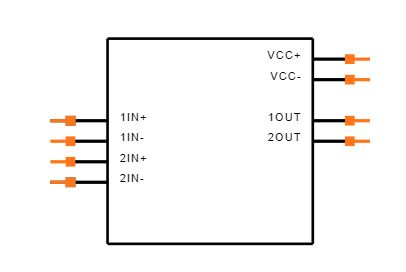
•Pin1(1OUT):Output of Op-Amp 1
•Pin2(1IN-):Inverting Input of Op-Amp 1
•Pin3(1IN+):Non-Inverting Input of Op-Amp 1
•Pin4(VCC-):Ground or Negative Supply Voltage
•Pin5(2IN+):Non-Inverting Input of Op-Amp 2
•Pin6(2IN-):Inverting Input of Op-Amp 2
•Pin7(2OUT):Output of Op-Amp 2
•Pin8(VCC+):Positive Supply Voltage
Ⅲ.Working principle of RC4558P
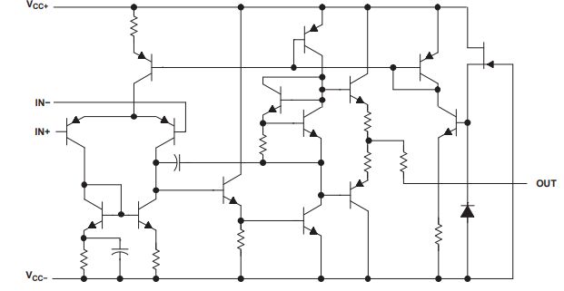
1.Differential amplifier: The core of the operational amplifier is the differential amplifier. A differential amplifier has two inputs (non-inverting and inverting) and one output. The basic working principle of a differential amplifier is to calculate the voltage difference between two input terminals and amplify it.
2.Feedback mechanism: RC4558P operational amplifier usually uses a negative feedback mechanism to stabilize and adjust its gain. Negative feedback is a feedback mechanism in which a portion of the output signal is used to influence the input signal, thereby changing the amplifier's gain and improving its stability. In the case of the RC4558P, negative feedback is achieved by directing a portion of the signal from the output back to the input. This feedback mechanism reduces the gain of the amplifier and increases its stability. By adjusting the strength of negative feedback, the gain and bandwidth of the amplifier can be controlled to meet the needs of a specific application.
3.Input and output: The input signal is input through the non-inverting input terminal and the inverting input terminal. The output signal is obtained through the output terminal. When the input signal is amplified, the output signal has a larger voltage amplitude relative to the input signal.
4.Ideal characteristics of operational amplifiers: An ideal operational amplifier has characteristics such as infinite gain, infinite input impedance, and zero output impedance. However, actual operational amplifiers have some non-ideal characteristics, such as limited gain, input bias current, input bias voltage, etc.
5.Power supply: RC4558P requires an appropriate power supply. Typically, it has a positive supply pin, a negative supply pin, and a ground pin to ensure the op amp is functioning properly.
6.Common mode rejection ratio (CMRR): Operational amplifiers are usually designed with a high common mode rejection ratio to reduce the impact from common mode components of the input signal. Common-mode rejection ratio refers to the degree to which the op amp rejects the common mode of the input signal (the signal that appears at both inputs at the same time).
Ⅳ.Application fields of RC4558P
1.Filter: Operational amplifier plays a very important role in the filter circuit. They amplify the input signal while rejecting or passing signals in a specific frequency range, depending on the type of filter designed. RC4558P is an operational amplifier that can be used to design various types of filters, including low-pass filters, high-pass filters, and band-pass filters. These filters are very useful in signal processing and different types of filters can be selected as needed to meet specific signal processing requirements.
•Low-pass filter: allows low-frequency signals to pass and suppresses high-frequency signals. This filter is often used to remove noise or high-frequency interference.
•High-pass filter: allows high-frequency signals to pass and suppresses low-frequency signals. This filter is often used to extract high-frequency components or eliminate low-frequency noise.
•Bandpass filter: allows signals within a specific frequency range to pass and suppresses signals at other frequencies. This type of filter is often used to extract signal components within a specific frequency range.
2.Laser driver: In the laser drive circuit, RC4558P can be used to control and amplify the laser drive signal.
3.Audio amplifier: RC4558P is very common in the design of audio amplifiers, especially for headphone amplifiers and power amplifiers. The high gain and low distortion characteristics of this op amp make it excellent in audio processing. In a headphone amplifier, the RC4558P can be used to increase the signal level, thereby providing clearer and louder audio for headphones. This amplifier usually has a low-pass filter attached to it to remove noise that may be caused by power lines or electromagnetic interference. In power amplifiers, the RC4558P can be used to drive speakers or other audio output devices. It converts weak audio signals into a current large enough to drive these devices to produce audible sound. Similar to headphone amplifiers, power amplifiers often have appropriate filters attached to improve audio quality.
4.Signal conditioning: RC4558P is often used in signal conditioning circuits to amplify, filter and adjust sensor signals to meet the requirements of subsequent processors or acquisition systems.
5.Instrument amplifier: In the design of instrument amplifier, RC4558P can be used to amplify and process the weak signals generated by the sensor, thereby improving the accuracy and sensitivity of the measurement system.
6.Power management: In power management circuits, RC4558P can be used to design voltage regulators and feedback amplifiers to control and adjust power output.
7.Audio equipment: Due to its advantages in audio applications, RC4558P can be used to design various audio equipment, such as power amplifiers, pre-amplifiers, etc.
8.Communication equipment: In communication equipment, RC4558P can be used to amplify and process analog signals, such as in modems, transceivers and other circuits.
Ⅴ.Absolute Maximum Ratings of RC4558P
over operating free-air temperature range (unless otherwise noted)
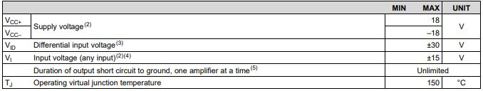
1.Stresses beyond those listed under Absolute Maximum Ratings may cause permanent damage to the device.These are stress ratings only, and functional operation of the device at these or any other conditions beyond those indicated under Recommended Operating Conditions is not implied. Exposure to absolute -maximum-rated conditions for extended periods may affect device reliability.
2.All voltage values,unless otherwise noted,are with respect to the midpoint between Vcc+ and Vcc–.
3.The magnitude of the input voltage must never exceed the magnitude of the supply voltage or 15V, whichever is less.
4.Differential voltages are at IN+ with respect to IN–.
5.Temperature and/or supply voltages must be limited to ensure that the dissipation rating is not exceeded.
Ⅵ.Electrical Characteristics of RC4558P
(at specified free-air temperature, Vcc+=15 V, Vcc–=–15 V)
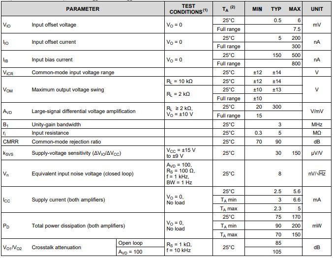
1.All characteristics are measured under open-loop conditions with zero common-mode input voltage, unless otherwise specified.
2.Full range is 0°C to 70°C for RC4558 and –40°C to 85°C for RC4558I.
Ⅶ.Performance of RC4558P at different temperatures
1.Temperature drift: The performance of an operational amplifier may have temperature drift, which refers to changes in its key parameters (such as gain, bias current, etc.) as temperature changes. Temperature drift can cause performance differences at different temperatures.
2.Gain temperature drift: The gain of an operational amplifier may drift with temperature changes. This means that the amplifier may amplify the input signal differently at different temperatures.
3.Temperature range: The RC4558P's data sheet or specification sheet will usually provide information about its performance over different temperature ranges. This includes typical operating and extreme temperature ranges.
4.Common mode rejection ratio (CMRR) temperature drift: CMRR refers to the degree of suppression of common mode signals by the operational amplifier. Temperature changes may cause changes in CMRR, thereby affecting the amplifier's ability to reject common-mode signals.
5.Input bias current and input bias voltage: These parameters may also change due to temperature. The temperature drift of input bias current and input bias voltage is one of the important factors affecting the performance of operational amplifiers.
Frequently Asked Questions
1.What is the typical voltage supply range for the RC4558P?
The RC4558P operational amplifier typically operates within a voltage supply range of ±4V to ±18V. This wide supply voltage range makes it versatile for various electronic applications.
2.Within what range can the RC4558P be safely powered?
RC4558P can generally operate under positive and negative symmetrical power supply voltages, and its recommended power supply voltage range is usually ±4V to ±18V. This means that the voltage difference between the positive and negative supplies should be within this range.
3.How many operational amplifiers are integrated into a single RC4558P package?
The RC4558P is a dual operational amplifier, meaning it contains two independent op-amp units within a single IC package. This dual configuration allows for more flexibility in circuit design and applications.
4.What is the frequency response range of RC4558P?
Typical frequency response range may be between a few hertz (Hz) to several megahertz (MHz), but the specific value will be affected by factors such as operating conditions, power supply voltage, load, etc.
5.How to protect the RC4558P amplifier from overvoltage?
Add an overvoltage protection circuit to the power supply circuit to prevent adverse effects on the RC4558P during overvoltage conditions. This can include overvoltage protection diodes, voltage limiters or transient voltage suppressors. Add appropriate protection circuitry, such as voltage limiters, amplifiers, or suppression circuits, to the RC4558P input and output to prevent input or output overvoltage.
6.What are the alternative models of RC4558P?
Alternative models of RC4558P include RC4558IP, RC4558PE4, TL072IPE4, etc.