By Texas Instruments 246
CD4017BE is one kind of integrated circuit, which belongs to CMOS (interchangeable metal semiconductor semiconductor) series. This is a 10-speed digital counter, usually used for electronic and on-line counting.
CD4017BE is a 5-line digital counter, each one has 10 lines. Includes import time, overlapping and time prohibition code. As a result, the "time signal input" signal is "low", the current time signal is changed, and the counter direction is calculated.
Ⅰ.CD4017BE's grading reference number
•Order:10 bit
•Packing/Box:PDIP-16
•Counter category:Decade
•Enjoyment series:CD4000
•Counting method:Synchronous
•Work power:3V to 1V
•Minimum working temperature:-55℃
•Maximum working temperature:+125℃
•Output current:+/- 1.5 mA
•Speed rate:11 MHz
•Number of legs:16
•Time frequency:11 MHz
•Electrical power:5.00V,10.0V,15.0V
•Number of access gates:1
•Number of imports:1
•Power source (Max):18V
•Power source (Min):3V
•Length:19.3 mm
•Degree:6.35 mm
•Altitude:4.57 mm
•Product life cycle:Active
•Counting speed rate:5.5 MHz
Ⅱ.CD4017BE basic working principle
CD4017BE is one 10-speed division counter, its basic working principle is 10 clocks, 10 clocks, 10 clocks, 10 clocks, and 10 clocks. CD4017BE basic working principle below:
1.CD4017BE is a one-to-one ten-step counting machine, and its functions can be controlled automatically when the key is received. At each time, the number of calculations increases as the number of calculations increases.
CD4017BE's pull leg arrangement below:
GND:Ground
VCC:Electric power (+5V)
Clear:Clear the import end, and the high voltage level is effective. At this time, when the power is high, the counter is zero.
Clock:Time input end. As the legs reach the top, the count of the calculator will increase.
Outputs:At the end of the journey, it is necessary to show the numerical tenor system.
Count Inputs:When the input end of the counter is connected to a low power supply, the input terminal is connected to a low power supply, so that when the input terminal is connected, the high power supply is switched to a low power supply.
2.Export control system: There are 10 foreign withdrawals, 0 to 9 in 10 consecutive orders. Each time when the explosion arrives, one of the foreigners will be very active, and the actual count will be displayed. For example, if the count is 3, the 4th person's exit leg (Q4) is very active.
3.Counting increase: CD4017BE is a one-to-one ten-step counting machine, equipped with equipment, counting time, etc. Input and withdrawal, and then show the required number for import and output. At normal times, when the power supply reaches high voltage, the counter's count increases to 0, and when the clock reaches the top of the grid, the counter's count increases. under there At one time, when the clock was on its way, the counter's count was increased to 3.4.The demand should be careful, but the CD4017BE's export could be withdrawn. This is also true, when a certain number of people in a certain number of calculations have a high power output, in normal times, the number of decimal systems in the system is 1. For example, if a certain person has a high-speed phone (representative 5), the actual count is 4.
4.Decal system count: CD4017BE's count is ten system, from 0 to 9. The number of counting machines increases at 9 o'clock, and the number of counting machines is 0 at the next hour. Various cyclical accounting characteristics can be used to show the numerical control or other demand-based cyclical functions.
5.Overlapping function: CD4017BE equipped with overlapping retracting leg (Reset), at present, when the retracting leg is engaged and the effect signal is reached, the counter position is 0. A new high-pressure calculator has been launched that can be used under certain conditions.
Ⅲ.Pin functions of CD4017BE
•Pin1 (MR): Master reset pin. When this pin receives a low level signal, the counter will be reset to 0.
•Pin2 (CP0): First clock input. This pin receives clock pulses and is used to control the increment of the counter.
•Pins3-9 (Q0-Q6): Output pins. These pins correspond to decimal 0 to 6. Whenever the counter increments to the corresponding value, the corresponding output pin goes high.
•Pin8 (GND): Ground. Connect to circuit ground.
•Pin10 (CE1): Enable input 1. When this pin receives a high level, the counter is enabled. Can be used to control the enabling and disabling of counters.
•Pin11 (CE2): Enable input 2. Similar to the CE1 pin, it is used to control the enabling and disabling of the counter.
•Pins12-15 (Q7-Q9, QA): Output pins. These pins correspond to decimal 7 through 9 and A. Like Q0-Q6, whenever the counter increments to the corresponding value, the corresponding output pin goes high.
•Pin16 (VDD): Positive supply voltage. Connect to positive power supply.
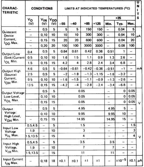
Ⅳ.Static Electrical Characteristics of CD4017BE
Ⅴ.Correctly connect and use the pins of CD4017BE
1.Power supply connections: Connect pin 16 (VDD) to the positive supply and pin 8 (GND) to the ground of the circuit.
2.Clock input connection: Connect the clock signal source to pin 2 (CP0).
3.Output connection: Connect the output pins (Q0-Q9, QA-QD) of the counter to other electronic components that need to be controlled. These components may include LEDs, digital displays, relays, etc., depending on your application.
4.Reset connection (optional): If you need to use the master reset function, connect pin 1 (MR) to logic low (usually ground).
5.Enable input connection (optional): If using the enable input, connect pin 10 (CE1) and/or pin 11 (CE2) to logic high.
6.Other connections (subject to requirements): Depending on the specific application, other pins may need to be connected to achieve specific functions. For example, pin 9 (Q6) can be connected to pin 15 (Q9) for extended counting.
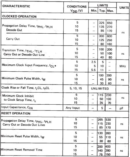
Ⅵ.Dynamic Electrical Characteristics of CD4017BE
Ⅶ.Common applications of CD4017BE
1.Digital display driver: The output of the CD4017BE counter can be connected to a digital LED display or digital tube to display different numbers. This property makes it useful in applications such as clocks, timers, and counters. Through programming, the output of the CD4017BE counter can be configured to display any desired number. This makes it ideal for a variety of applications such as counting, timing and displaying time.
2.Timer: CD4017BE can be used to build a simple timer circuit that controls the output to represent the elapsed time.
3.Cycling light effects: Since CD4017BE can cycle count in a specific order, it is often used to create cyclic lighting effects, such as marquees.
4.Flip-flop and timing control: CD4017BE is a decimal counter with a built-in decoder that can be used for flip-flops and timing control applications. It has 10 output pins that can be used to implement various logic functions. To implement the trigger and timing control functions, the input pins of the CD4017BE (e.g., CP, CR, etc.) need to be connected to an appropriate signal source to trigger the operation of the counter at a specific moment. At the same time, the output pins of the counter also need to be connected to other logic circuits or components to implement the exposed logic functions. By choosing the appropriate connection method, CD4017BE can be used to implement various logic functions, such as edge flip-flops, JK flip-flops, T flip-flops, monostable flip-flops, etc. In addition, CD4017BE can also be used to implement timing control functions, such as frequency dividers, delays, synchronizers, etc.
5.Frequency divider: Since the CD4017BE is a frequency divider counter, it can be used to divide the input frequency into lower frequencies, thereby playing a role in timing and timing applications.
6.Electronic games and toys: In some electronic games and toys, the CD4017BE is used to create specific sequences and effects, such as looping flashing lights or sound effects.
7.Educational use: CD4017BE is an experimental device very suitable for digital logic and electronic circuit education. Its function is relatively simple, easy to understand and use, and it also has a built-in decoder that can easily implement various logic functions. By experimenting and learning to use the CD4017BE, students can better understand the working principles and implementation methods of digital logic circuits. They can use it to implement various logic functions, such as edge flip-flops, JK flip-flops, T flip-flops, etc., and verify their correctness by observing and measuring the output results. In addition, students can also learn how to use CD4017BE to implement timing Control functions such as dividers, delays, etc.
8.Automated control system: In some automated control systems, CD4017BE can be used to control the sequence of specific events or actions.
Ⅷ.Alternate model of CD4017BE
1.MC14517B(ON Semiconductor): This is an alternative model of ON Semiconductor (formerly Motorola), which is also a divided decimal counter.
2.74HC4017(NXP): This is the decimal division counter of the 74HC series produced by NXP, similar to the CD4017BE.
3.CD4022BE:This is another CD40xx series counter. It is an 8-bit binary counter and has different functions from CD4017BE.
4.CD4510BE:This is another counter in the CD40xx series. It is a 4-bit binary/decimal variable counter.
Frequently Asked Questions
1.What counting modes does CD4017BE support?
CD4017BE supports sequential counting, enable and disable modes, reset mode, and cascade mode.
2.How is the CD4017BE typically powered?
The CD4017BE is typically powered by connecting the VDD pin to a positive power supply and the GND pin to the ground.
3.How does the CD4017BE handle clock pulses in its operation?
On each rising edge of the clock input (CP0), the CD4017BE advances its count by one. When it reaches 9, the next clock pulse resets the counter to 0.
4.In what applications is the CD4017BE commonly used?
The CD4017BE is commonly used in applications such as digital displays, sequential LED lighting, timers, frequency dividers, and various other digital logic and counting applications.
5.What is the purpose of the Master Reset (MR) pin on the CD4017BE?
The Master Reset (MR) pin is used to reset the counter to zero when it receives a low signal. It is a way to force the counter to start counting from the beginning.